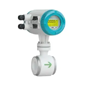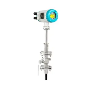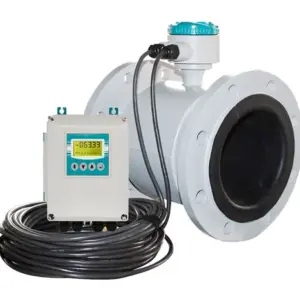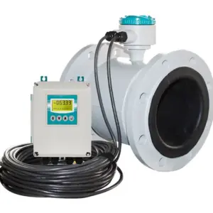
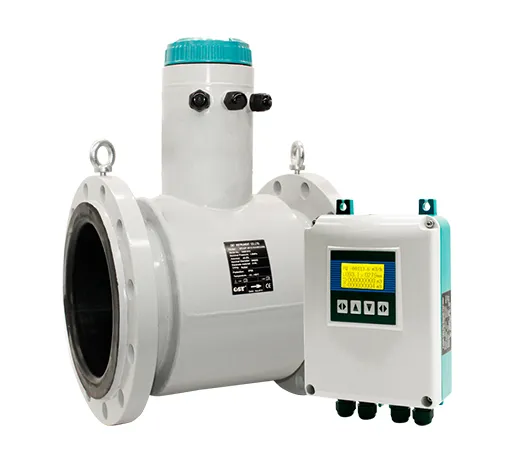
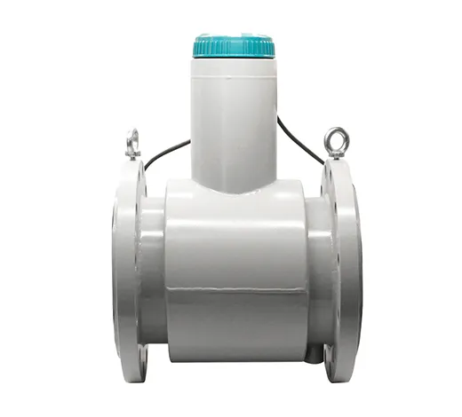
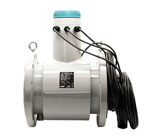
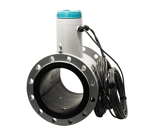
Partially filled pipe electromagnetic flow meter can measure partially filled pipe liquid flow, it is very popular in irrigation.
Its can use solar power supply, this type is very suitable for remote areas where has no industrial power supply.
It adopts safe and durable material, service life is longer than normal products. Normally, it can work at least 5-10 years or longer.
And we have already got food grade certificate for its liner so it can be used for drinking water, underground water, etc. Many drinking water company use this type in their big size pipeline.
We use an accurate mini ultrasonic level meter for its liquid level measurement then the flow meter will record the liquid level and use this parameter to measure liquid flow. This ultrasonic level meter’s blind area is very small and its accuracy can reach to ±1mm.
Application
| Measuring Pipe Size | DN200-DN3000 |
| Connection | Flange |
| Liner Material | Neoprene/Polyurethane |
| Electrode Marerial | SS316, TI, TA, HB, HC |
| Structure Type | Remote Type |
| Accuracy | 2.5% |
| Output Signal | Modbus RTU, TTL electrical level |
| Communication | RS232/RS485 |
| Flow speed range | 0.05-10m/s |
| Protection Class | Converter: IP65
Flow Sensor: IP65(standard), IP68(optional) |
.jpg)
Drawing ( DIN Flange )
|
||||||
| Diameter
(mm) |
Nominal
pressure |
L(mm) | H | φA | φK | N-φh |
| DN200 | 0.6 | 400 | 494 | 320 | 280 | 8-φ18 |
| DN250 | 0.6 | 450 | 561 | 375 | 335 | 12-φ18 |
| DN300 | 0.6 | 500 | 623 | 440 | 395 | 12-φ22 |
| DN350 | 0.6 | 550 | 671 | 490 | 445 | 12-φ22 |
| DN400 | 0.6 | 600 | 708 | 540 | 495 | 16-φ22 |
| DN450 | 0.6 | 600 | 778 | 595 | 550 | 16-φ22 |
| DN500 | 0.6 | 600 | 828 | 645 | 600 | 20-φ22 |
| DN600 | 0.6 | 600 | 934 | 755 | 705 | 20-φ22 |
| DN700 | 0.6 | 700 | 1041 | 860 | 810 | 24-φ26 |
| DN800 | 0.6 | 800 | 1149 | 975 | 920 | 24-φ30 |
| DN900 | 0.6 | 900 | 1249 | 1075 | 1020 | 24-φ30 |
| DN1000 | 0.6 | 1000 | 1359 | 1175 | 1120 | 28-φ30 |
| QTLD/F | X | X | X | X | X | X | X | X | X | |
| Caliber size | DN80-DN3000(3″-120″) | |||||||||
| Structure | Remote | 1 | ||||||||
| Remote with explosion proof | 2 | |||||||||
|
Lining Material |
Neoprene | 1 | ||||||||
| FEP | 2 | |||||||||
| PFA | 3 | |||||||||
| PTFE | 4 | |||||||||
| Polyurethane | 5 | |||||||||
| Hard Rubber | 6 | |||||||||
| Others | 7 | |||||||||
|
Electrode Material |
SS316L | 1 | ||||||||
| Hastelloy B | 2 | |||||||||
| Hastelloy C | 3 | |||||||||
| Titanium | 4 | |||||||||
| Tantalum | 5 | |||||||||
| Platinum-iridium | 6 | |||||||||
| Stainless steel covered with tungsten carbide | 7 | |||||||||
| Others | 8 | |||||||||
| Sensor Material | Carbon Steel | 1 | ||||||||
| SS304 | 2 | |||||||||
| SS316 | 3 | |||||||||
| Power Supply | 20~36 VDC | G | ||||||||
| 85~265 VAC | E | |||||||||
| 9~36 VDC solar power | SD | |||||||||
| Others | X | |||||||||
|
Signal Output /Communication |
4~20 mA + Pulse + RS485 MODBUS | A | ||||||||
| 4~20 mA + HART | B | |||||||||
| 4~20 mA + Profibus | C | |||||||||
| GPRS | D | |||||||||
|
Flange Standard |
DIN D6:DIN PN6, D10: DIN PN10, D16: DIN PN16 | D** | ||||||||
| ANSI A15: ANSI 150# | A** | |||||||||
| JIS J10: JIS 10K, J20: JIS 20K, J30: JIS 30K | J** | |||||||||
| Others | O | |||||||||
| Protection Grade | IP65 Transmitter + IP65 sensor | 1 | ||||||||
| IP65 Transmitter + IP68 sensor | 2 | |||||||||
Installation
1.Installation
Partially filled electromagnetic flow meter should be installed correctly to ensure good measurement. Normally we need leave 10D(10 times of diameter) straight pipe distance before partially filled pipe electromagnetic flow meter and 5D behind partially filled pipe electromagnetic flow meter. And try to avoid elbow/valve/pump or other device which will influent the flow speed. If the distance is not enough, then please install flow meter according to follow picture.
.jpg)
lnstall at the lowest point and vertical upward direction
Don’t install at the highest point or vertical downward diection |
.jpg)
When drop is more than 5m, install exhaust
valve at the downstream |
.jpg)
lnstall at the lowest point when used in open drain pipe
|
.jpg)
Need 10D of upstream and 5D of downstream
|
.jpg)
Dont’ install it at the entrance of pump, install it at the exit of pump
|
.jpg)
lnstall at the rising direction
|
2.Maintenance
Routine maintenance: only need to make periodic visual inspections of the instrument, check the environment around the instrument, remove dust and dirt, ensure that no water and other substances enter, check whether the wiring is in good condition, and check whether there are newly installed strong electromagnetic field equipment or newly installed wires near the instrument Cross-instrument. If the measuring medium easily contaminates the electrode or deposits in the measuring tube wall, it should be cleaned and cleaned regularly.
3.Fault finding: if the meter is found to work abnormally after the flow meter has been put into operation or normal operation for a period of time, the external conditions of the flow meter should be checked first, such as whether the power supply is good, whether the pipeline is leaking or in a state of partial pipe, whether there is any in the pipeline Whether air bubbles, signal cables are damaged, and whether the output signal of the converter (that is, the input circuit of the subsequent instrument) is open. Remember to dismantle and repair the flow meter blindly.
4.Sensor inspection
5.Converter check