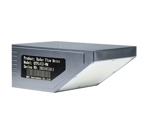
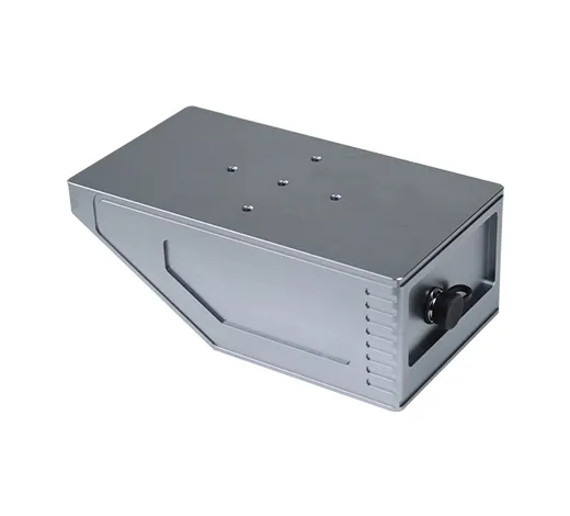
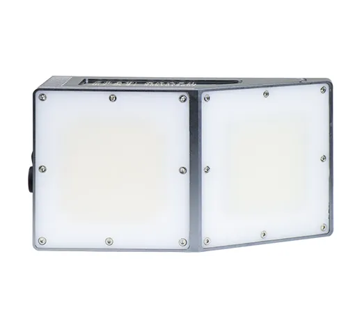
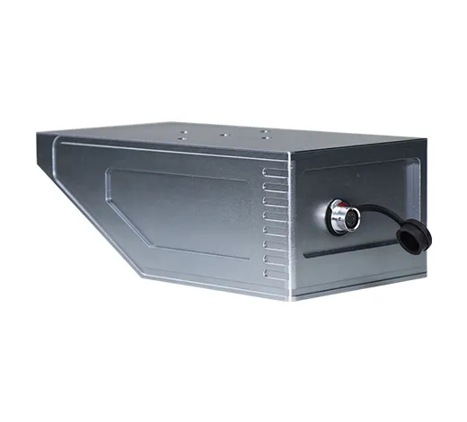
Radar flow meters are widely used in hydrological surveys, surface water resources monitoring, water measurement and metering in irrigation areas, river channel monitoring, as well as natural waters such as rivers, reservoirs, lakes, tides, irrigation channels (open channels), river channels, and farmland pipelines. Water monitoring.
Radar flow meter is also suitable for urban water logging, urban sewage, municipal water intake and drainage water monitoring, flood control, flood control, underground pipe network and other water level monitoring as well as drainage pipe network, drainage outlet, hydropower station ecological discharge flow monitoring and other fields, suitable for regular and irregular sections.
The radar flow measurement system can realize all-weather automatic collection and real-time monitoring of open channel, natural river flow and water data.
Technical Data
Table 1: Working Condition Parameters
| Parameter |
Description |
| Supply Voltage |
DC 7 ~ 24V |
| Current(12V Power Supply) |
About 300mA in normal operation, and less than 1mA in sleep mode. |
| Working Temperature |
-35℃ ~ 70℃ |
| Protection Class |
IP67 |
| Emission Frequency |
24.000 ~ 24.250GHz |
| Communication Interface |
RS-232 / RS-485 |
| Communication Protocol |
MODBUS-RTU / Customized Protocol / SZY206-2016 “Water Resources Monitoring Data Transmission Protocol” |
Table 2: Measurement Parameters
| Parameter |
Description |
| Velocity Range |
0.15 ~ 15m/s |
| Velocity Accuracy |
±1% FS, ±2.5% of reading |
| Velocity Resolution |
0.01m/s |
| Distance Range |
1.5 ~ 40m |
| Distance Accuracy |
±1mm |
| Distance Resolution |
1mm |
| Antenna Beam Angle |
Flow Velocity:14 x 32゜
Water level:11 x 11゜ |
| Interval Time |
1 ~ 5000min |
Table 3: Appearance Parameters
| Parameter |
Description |
| flow meter Size ( LxWxH) |
302×150×156mm |
| Support Size ( LxWxH) |
100×100×100mm |
| Weight |
flow meter + support: 5.8kg |
| Housing Material |
Galvanized, stainless steel sheet |
Installation
The installation of radar flow meter must pay attention that the direction of radar wave propagation cannot be blocked by objects, otherwise the radar signal will be attenuated and the measurement will be affected. When installing on the side, it is recommended that the horizontal rotation angle should not exceed the range of 45-60 degrees.
Considering different working conditions, we first need to consider the following 2 factors:
1. Antenna Beam Range
The flow meter integrates a radar level meter and a radar velocimeter. The radar antenna beam angle of the radar level meter is 11°×11°, and the antenna beam angle of the radar velocimeter is 14×32°. When the level meter illuminates the water surface, the irradiation area is similar A circle, when the velocimeter illuminates the water surface, the illuminated area is similar to an elliptical area, as shown in Figure 1.1. Accurately understanding the illumination range of radar waves helps to choose a suitable place to install and avoid some scenes that are easily disturbed, such as rivers on both sides of the river, like the branches swinging in the wind.
Figure 1.1 Installation of 10-meter radar level meter and a radar velocimeter antenna irradiation area
The boundary of the water surface area illuminated by the radar is proportional to the installation height. Table 1.2 shows the parameter values of A, B, and D when the beam of the radar level mete and the radar velocimeter illuminates the water surface when the installation height is 1 meter (see Figure 1.1 for the meanings of A, B, and D). , the actual installation height (unit meter) multiplied by the following value is the actual corresponding parameter
| Name |
Length(m) |
| Radar velocimeter A |
0.329 |
| Radar velocimeter B |
0.662 |
| Radar level gauge diameter D |
0.192 |
1.2 Antenna beam irradiation surface parameter values
Influence of installation height on current measurement
Under the same conditions, the higher the installation height, the weaker the echo and the worse the signal quality. Especially in the scene with low water flow speed, the ripple is small, which is more difficult to detect. At the same time, the area of the radar wave irradiation area will be larger, and the beam irradiation may be When it reaches the bank of the canal, it is affected by the moving target on the bank. If the installation is too low, it is not conducive to anti-theft protection, so for pole installation, it is recommended that the installation height range is 3-4 meters.
In addition to the above two points, the specific requirements are as follows:
1) When installing the flow meter, the liquid level meter and the flow meter radar cannot be blocked, otherwise the measurement accuracy will be affected; there is no huge stone block water in the detection channel section, no huge vortex, turbulent flow and other phenomena;
2) The detection channel should be as straight as possible, stable and concentrated;
3) The radar velocimeter is only affected by the dynamic target. When the channel is hardened and there are no weeds or trees, even if the beam is irradiated on both sides of the channel, it will not affect the flow measurement. In addition, the flow measurement section is as regular as possible;
4) The detection channel section should be kept smooth to prevent the accumulation of floating objects.
5) The beam of the current meter is recommended to face the direction of the incoming water, as shown in Figure 1.1, and the horizontal angle to the direction of the water flow is 0 degrees.
6) When installing the flow meter, try to ensure that the upper surface of the casing is level and installed in the middle of the channel.