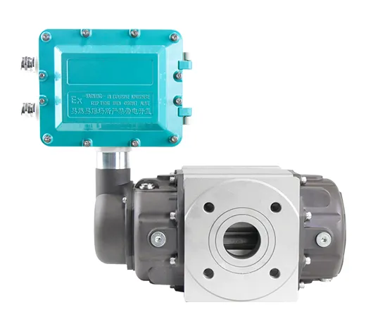
Application
| Size | DN25-DN200mm |
| Accuracy | 1.5% (Standard) Qt—Qmax ±1.5%,Qmin—Qt ±3.0%,Qt=0.05Qmax 1.0% (Optional) Qt—Qmax ±1.5%,Qmin—Qt ±3.0%,Qt=0.05Qmax |
| Repeatability | Better than 0.2% |
| Working condition | Ambient: -30℃~+60℃ Medium temperature:-20℃~+80℃ Relative humidity: 5%-9% |
| Power supply | External power: +12~24VDC Internal power:3.6V Battery |
| Power consumption | <2W (external power) ≤1mW (internal power) |
| Output | Pulse 4-20mA (external power) |
| Communication | RS485 |
| Pressure rating | 1.6MPa |
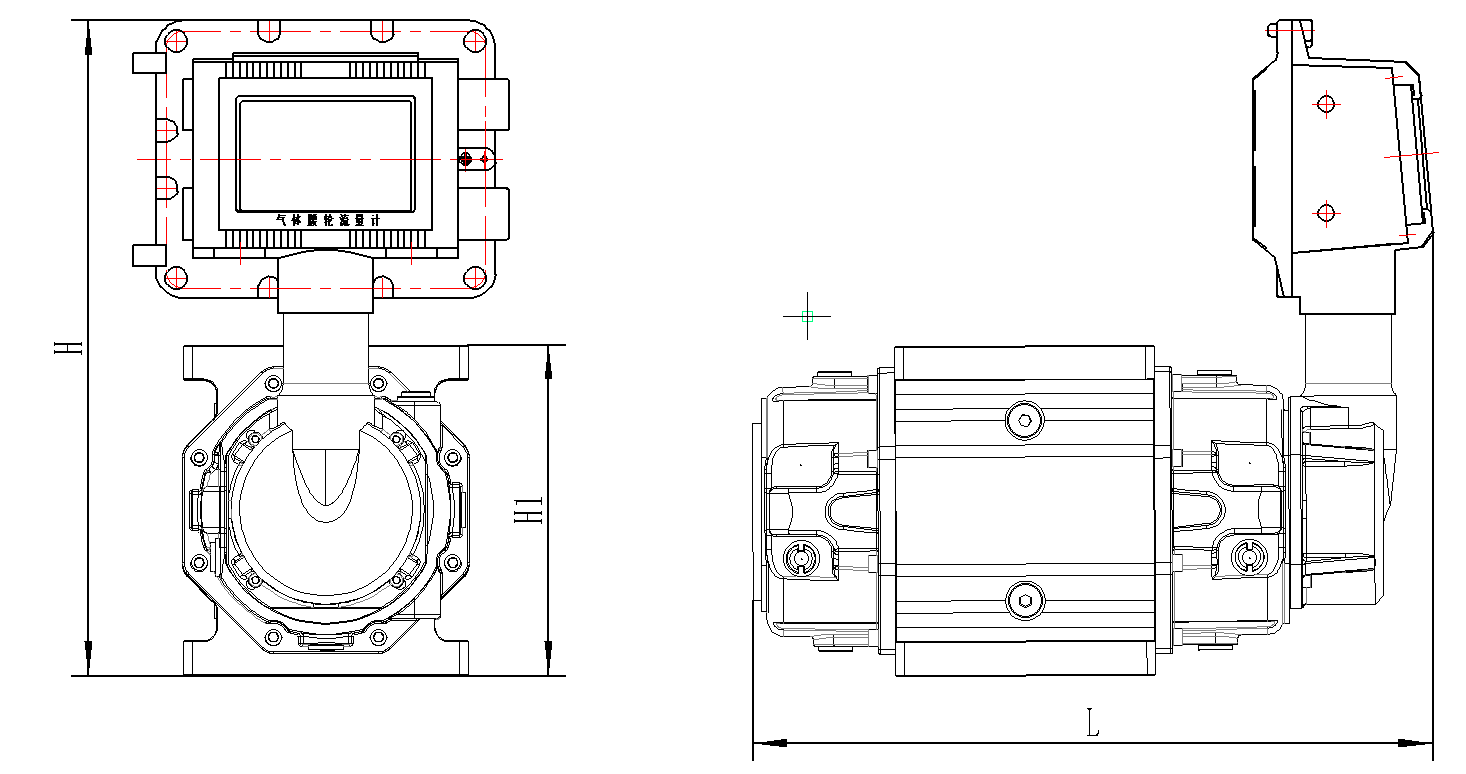
| Model | Flow Spec | L | H1 | H | Remark |
| QTLL-25 | G16 | 273 | 128 | 340 | Flange dimension refer to PN1.6MPa GB flange. Other flange standards can specially make. While installation, please consider the sealing gasket thickness about 2-3mm. |
| QTLL-40 | G25 | 354 | 190 | 375 | |
| QTLL-50 | G25 | 354 | 190 | 375 | |
| G40 | 425 | 190 | 375 | ||
| G65 | 425 | 190 | 375 | ||
| QTLL-80 | G65 | 412 | 190 | 375 | |
| G100 | 412 | 190 | 375 | ||
| G160 | 475 | 245 | 400 | ||
| QTLL-100 | G160 | 575 | 245 | 400 | |
| G250 | 665 | 245 | 400 | ||
| QTLL-150 | G400 | 683 | 460 | 505 | |
| G650 | 802 | 460 | 505 |
| Model | Flow Spec |
Size (mm) |
Flow Range (m³/h) |
Start up flow (m³/h) |
Max Pressure loss (KPa) |
| QTLL-25 | G16 | DN25 | 1-25 | 0.05 | 0.08 |
| QTLL-40 | G25 | DN40 | 1-40 | 0.05 | 0.08 |
| QTLL-50 | G25 | DN50 | 1-40 | 0.1 | 0.08 |
| G40 | 2-65 | 0.1 | 0.1 | ||
| G65 | 2-100 | 0.12 | 0.15 | ||
| QTLL-80 | G65 | DN80 | 2-100 | 0.12 | 0.15 |
| G100 | 2.5-160 | 0.1 | 0.15 | ||
| G160 | 3-250 | 0.1 | 0.18 | ||
| QTLL-100 | G160 | DN100 | 3-250 | 0.1 | 0.2 |
| G250 | 4-500 | 0.65 | 0.35 | ||
| QTLL-150 | G400 | DN150 | 8-650 | 0.76 | 0.46 |
| G650 | 15-1000 | 0.85 | 0.5 | ||
| QTLL-200 | G1600 | DN200 | 32-1600 | 0.95 | 0.6 |
| QTLL | Parameters | ××× | × | × | × | × | × | × |
| Size (mm) | DN25-DN200mm | |||||||
| Accuracy | 1.5% (standard) | 1 | ||||||
| 1.0% | 2 | |||||||
| Nominal Pressure | 1.0MPa | 1 | ||||||
| 1.6MPa | 2 | |||||||
| Others | 3 | |||||||
| Body Material | Aluminum Alloy | A | ||||||
| Stainless Steel | S | |||||||
| Output/ Communication |
Pulse | 1 | ||||||
| Pulse+4~20mA | 3 | |||||||
| Pulse+4~20mA+RS485 | 4 | |||||||
| Power Supply | Battery Powered | 1 | ||||||
| Battery Powered + External Power DC24V | 2 | |||||||
| Ex-proof | With | 1 | ||||||
| Without | 2 | |||||||
| Installation | Horizontal | H | ||||||
| Vertical | V | |||||||
Installation
(1)Vertical installation
When installing vertically, the gas inlet should be at the top, and the airflow will flow from top to bottom, that is, top in and bottom out. The company recommends users to use vertical installation as much as possible. The self-cleaning ability of the rotor to sundries;
Vertical%20installation.png)
(2)Horizontal installation
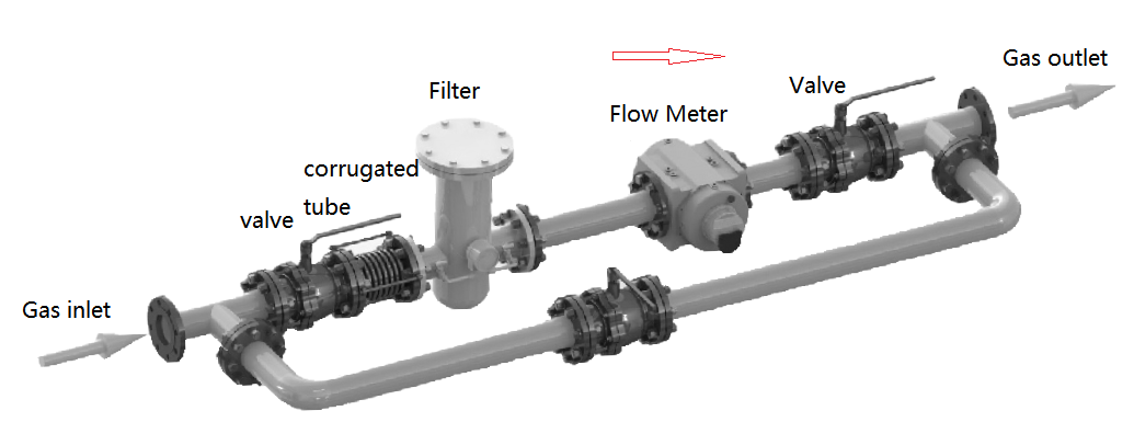
When installing horizontally, the axis of the inlet and outlet ends of the flow meter should not be lower than the axis of the pipeline to prevent impurities in the gas from staying in the flow meter and affecting normal operation. At the same time, the flow meter flange should be directly connected to the filter flange;