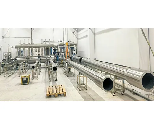
Cases
Technical Data
The Critical Flow Venturi Nozzle achieves high-precision gas flow measurement using the “choked flow” principle. As gas accelerates through the converging throat, velocity increases with pressure differential. When the downstream-to-upstream pressure ratio falls below the critical value (typically 0.528), the throat velocity reaches sonic speed, creating “critical flow.” At this point, further downstream pressure reduction no longer increases flow rate, which depends solely on upstream stagnation pressure and temperature. This characteristic isolates measurement from downstream disturbances, achieving accuracy up to ±0.2%
| Model | QGCS-Q1000 | QGCS-Q3000 | QGCS-Q4000 | QGCS-Q5000 |
| Size | DN15-DN100 | DN15-DN150 | DN15-DN200 | DN15-DN300 |
| Max Flow(m3) | 1000 | 3000 | 4000 | 5000 |
| Area(LxWxH) m | 10 x 4 x 3.5 | 12 x 6 x3.5 | 16 x 6 x 3.5 | 18 x 8 x 3.5 |
| Consumption(KW) | ≤32 | ≤80 | ≤107 | ≤132 |
| Uncertainty | ≤0 . 33% | |||
| Accuracy | Absolute pressure transmitter: 0.075% ~ 0. 1% Temperature sensor: 0.2% Humidity sensor: 2% Critical flow nozzle: 0.2% |
|||
| Collect Signal | Pulse, 4~20 mA | |||
| Wetted Parts | SS304 | |||
| Flow | Min standard: 0.016 m3/h, normal standard: Qm=2n | |||
| Working Environment | Atmospheric pressure: 86 ~ 104KPa Relative humidity: 40% ~90%RH | |||
| Design Standard | lSO 9300:2005, GB/T 21188-2007 | |||
Drawing (Design according to clients’ requirements)
.png) |
.png) |
| QGCS-Q1000 | QGCS-Q3000 |
.png) |
.png) |
| QGCS-Q4000 | QGCS-Q5000 |
Configuration
| QGCS-Q1000 | DN50/DN100 |
| QGCS-Q3000 | DN25/DN50/DN80/DN100/DN150 |
| QGCS-Q4000 | DN50/DN80/DN100/DN150/DN200 |
| QGCS-Q5000 | DN50/DN100/DN150/DN200/DN300 |
|
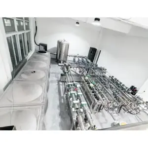
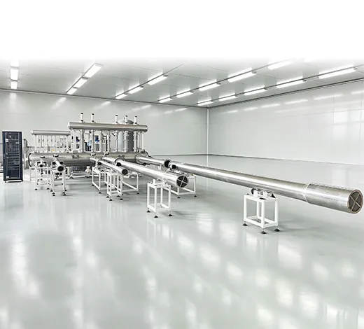
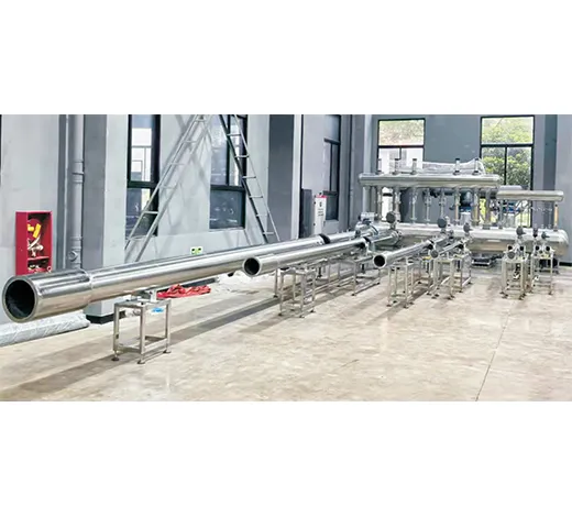
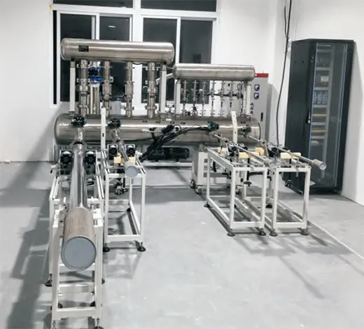
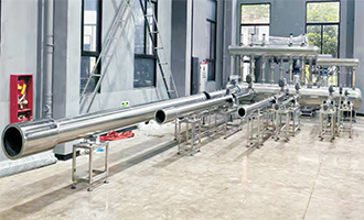
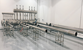
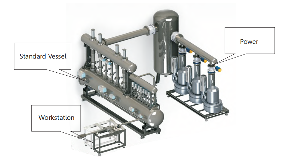
It consists of a stagnation vessel, a large-area vacuum vessel, a small-area vacuum vessel, standard flow meters (Critical Flow Venturi Nozzles), vacuum valves, connecting pipelines, and structural component
|
|
Pressure Measurement: The pressure data upstream and downstream of the Critical Flow Venturi Nozzles are respectively collected from the stagnation vessel and the large/small vacuum vessels.
|
|
Modular Design: The entire standard device module features a skid-mounted design, which facilitates easy installation and future expansion.
|
|
Installation Method: The Critical Flow Venturi Nozzles are installed on the stagnation vessel using the upstream large-space method (or “stagnation chamber” method)
|
Software
.png)
| 1. Self-diagnostic function | 2. Customizable calibration data format |
| 3. Adaptive power system | 5. Selectable data forms / Optional data templates |
| 6. On-site verification of nozzle coefficient / Field calibration of nozzle coefficient | 4. Arbitrary matching of flow points / Flexible flow point matching |