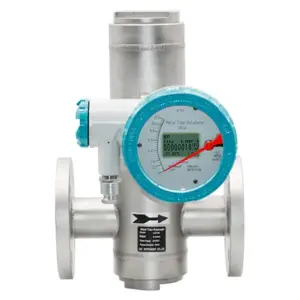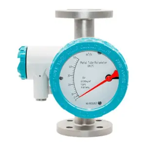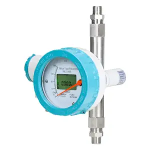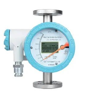
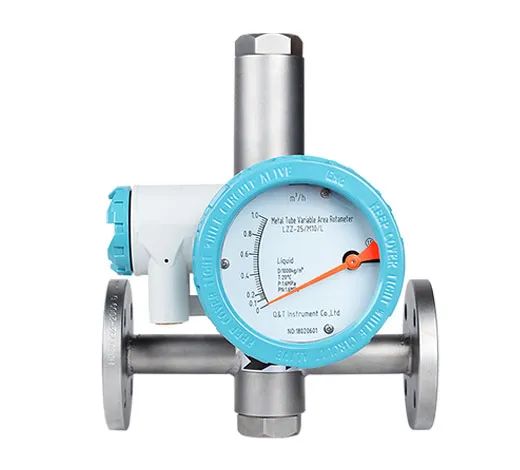
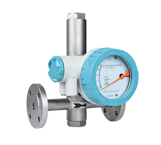
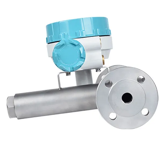
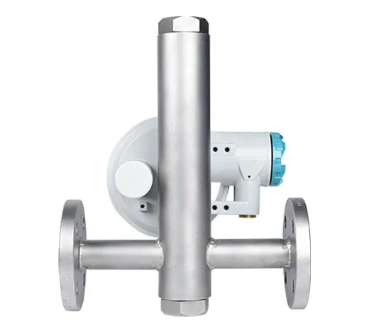
Application
| Measuring range | Water (20℃) 16~150000 l/h.
Air(0.1013MPa 20℃) 0.5~4000 m3/h. |
| Range ratio | 10:1(Special type 20:1). |
| Accuracy class | 2.5(Special type 1.5% or 1.0%). |
| Working pressure | DN15~DN50 PN16 (Special type 2.5MPa).
DN80~DN150 PN10 (Special type 1.6MPa). Pressure rating of jacket 1.6MPa. |
| Medium temperature | Normalized type -80℃~+220℃.
High-temperature type 300℃. Lined with FEP type ≤85℃. |
| Ambient temperature | -40℃~+120℃(Remote display without LCD≤85℃).
(Remote display with LCD≤70℃). |
| Dielectric viscosity | 1/4” NPT, 3/8” NPT 1/2” NPT≤5mPa.s
3/4” NPT,1” NPT ≤250mPa.s |
| Output | Standard signal: two-wire system 4 ~ 20mA (with HART communication).
Standard signal: three-wire system 0 ~ 10mA. Alarm signal:1.Two-way relay output. 2.One-way or two-approach switches . Pulse signal output: 0-1KHz isolated output. |
| Process connection | Standard type:24VDC±20%.
AC type:220VAC(85~265VAC) (optional). |
| Connection mode | Flange
Thread Tri-clamp |
| Levels of protection | IP65/IP67. |
| Ex-mark | Intrinsically safe:ExiaIICT3~6. Exd type:ExdIICT4~6. |
| Caliber
(mm) |
Work number | Flow range | Pressure loss kpa | ||||
| Water L/h | Air m3/h | Water Kpa | Air | ||||
| Normal type | Anti-corrossion type | Normal type Anti-corrossion type |
Normal type | Anti-corrossion type | |||
| 15 | 1A | 2.5~25 | — | 0.07~0.7 | 6.5 | – | 7.1 |
| 1B | 4.0~40 | 2.5~25 | 0.11~1.1 | 6.5 | 5.5 | 7.2 | |
| 1C | 6.3~63 | 4.0~40 | 0.18~1.8 | 6.6 | 5.5 | 7.3 | |
| 1D | 10~100 | 6.3~63 | 0.28~2.8 | 6.6 | 5.6 | 7.5 | |
| 1E | 16~160 | 10~100 | 0.48~4.8 | 6.8 | 5.6 | 8.0 | |
| 1F | 25~250 | 16~160 | 0.7~7.0 | 7.0 | 5.8 | 10.8 | |
| 1G | 40~400 | 25~250 | 1.0~10 | 8.6 | 6.1 | 10.0 | |
| 1H | 63~630 | 40~400 | 1.6~16 | 11.1 | 7.3 | 14.0 | |
| 25 | 2A | 100~1000 | 63~630 | 3~30 | 7.0 | 5.9 | 7.7 |
| 2B | 160~1600 | 100~1000 | 4.5~45 | 8.0 | 6.0 | 8.8 | |
| 2C | 250~2500 | 160~1600 | 7~70 | 10.8 | 6.8 | 12.0 | |
| 2D | 400~4000 | 250~2500 | 11~110 | 15.8 | 9.2 | 19.0 | |
| 40 | 4A | 500~5000 | 300~3000 | 12~120 | 10.8 | 8.6 | 9.8 |
| 4B | 600~6000 | 350~3500 | 16~160 | 12.6 | 10.4 | 16.5 | |
| 50 | 5A | 630~6300 | 400~4000 | 18~180 | 8.1 | 6.8 | 8.6 |
| 5B | 1000~10000 | 630~6300 | 25~250 | 11.0 | 9.4 | 10.4 | |
| 5C | 1600~16000 | 1000~10000 | 40~400 | 17.0 | 14.5 | 15.5 | |
| 80 | 8A | 2500~25000 | 1600~16000 | 60~600 | 8.1 | 6.9 | 12.9 |
| 8B | 4000~40000 | 2500~25000 | 80~800 | 9.5 | 8.0 | 18.5 | |
| 100 | 10A | 6300~63000 | 4000~40000 | 100~1000 | 15.0 | 8.5 | 19.2 |
| 150 | 15A | 20000~100000 | — | 600~3000 | 19.2 | — | 20.3 |
| QTLZ | X | X | X | X | X | X | X | X | X |
| Indicator | Code | ||||||||
| Local indicator | Z | ||||||||
| LCD indicator with ouput | D | ||||||||
| Norminal diameter | Code | ||||||||
| DN15 | -15 | ||||||||
| DN20 | -20 | ||||||||
| DN25 | -25 | ||||||||
| DN40 | -40 | ||||||||
| DN50 | -50 | ||||||||
| DN80 | -80 | ||||||||
| DN100 | -100 | ||||||||
| DN150 | -150 | ||||||||
| Structure | Code | ||||||||
| Bottom-top | / | ||||||||
| Left-right (horizontal) | H1 | ||||||||
| Right-left (horizontal) | H2 | ||||||||
| Side-side | AA | ||||||||
| Bottom -side | LA | ||||||||
| Thread connection | S | ||||||||
| Tri-clamp | M | ||||||||
| Body material | Code | ||||||||
| 304SS | R4 | ||||||||
| 316LSS | R6L | ||||||||
| Hastelloy C | Hc4 | ||||||||
| Titanium | Ti | ||||||||
| Liner F46(PTFE) | F | ||||||||
| Monel | M | ||||||||
| Indicator type | Code | ||||||||
| Iinear indicator(pointer indication) | M7 | ||||||||
| Nonlinear indicator(LCD Display) | M9 | ||||||||
| Combination function(only for LCD display) | Code | ||||||||
| 24VDC with 4~20mA output | S | ||||||||
| 24VDC with HART communication | Z | ||||||||
| Battery power | D | ||||||||
| Additional function | Code | ||||||||
| Measuring tube with thermal preservation / heat insulation jacket | T | ||||||||
| Measure medium temperature higher than 120.C | HT | ||||||||
| Ex-proof: | Code | ||||||||
| With | W | ||||||||
| Without | N | ||||||||
| Alarm | Code | ||||||||
| One alarm | K1 | ||||||||
| Two alarm | K2 | ||||||||
| None | N | ||||||||
Installation
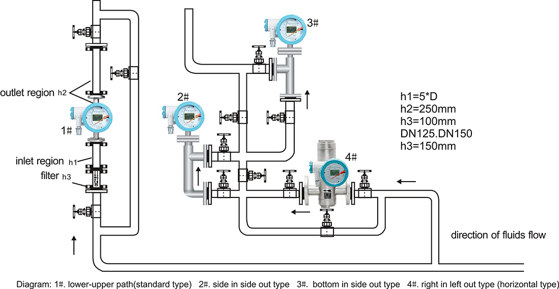
1. For flow meter installed,ensure the measuring pipe perpendicularity is better than 5 and should be equipped with bypass,easy to maintain and clean and does not affect production..
2. Monitoring and control system in the control valve,should be installed downstream of the flowmeter.For gas measurement,Should ensure the working pressure is not less than 5 times of pressure loss of the flowmeter, to make stable work of the flowmeter.
3. Before install the flowmeter,The pipe should be welding slag purging clean;When installation to remove locking component in the flow meter;when used after installation,Slowly open the control valve,Avoid shock damage flow meter